Ground Resistance Testing: How to Check a Doubtful Reading
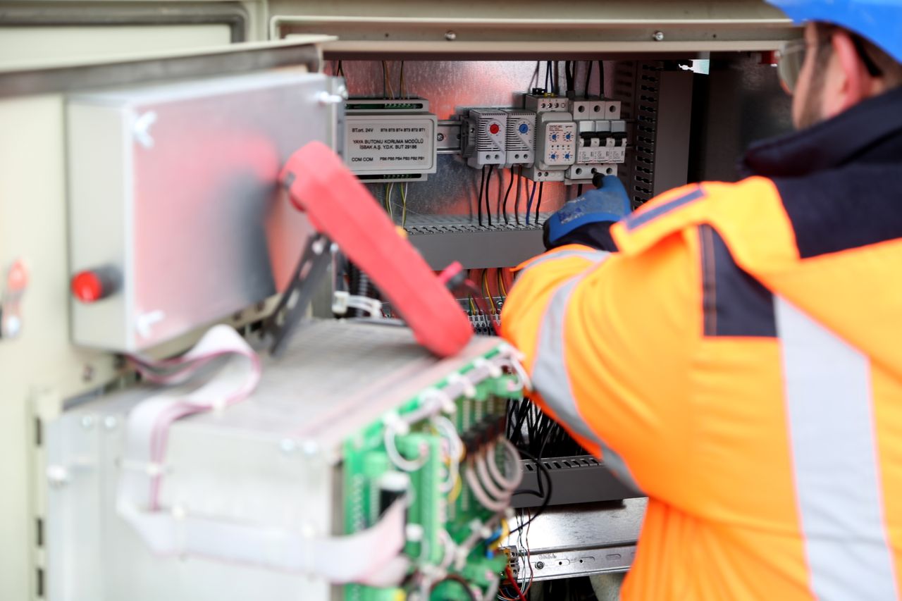
During a routine grounding system inspection, a technician measures a ground rod at a small commercial site. Last spring, the record showed 18 Ω. Today, the display reads 41 Ω. The rod looks intact, the clamp is in place, and the site appears unchanged.
A result like this raises two separate questions. The first is whether the grounding installation has deteriorated. The second is whether the measurement itself can be trusted. Answering them in the wrong order can lead to an unnecessary rod replacement or, in the opposite case, to a real problem being dismissed as a test error.
This article explains what a ground resistance value represents, why it shifts with site conditions and test arrangements, and how to check a doubtful result before acting on it.
What a Ground Resistance Reading Does
A ground resistance reading shows how easily current flows from a grounding electrode into the surrounding earth. It describes one property of the installation, and understanding its limits starts with what the instrument is measuring.
How the Electrode and Surrounding Soil Influence the Result
During ground resistance testing, the instrument passes a known current between the electrode and a remote point in the earth, then measures the voltage that this current produces. The ratio of the two gives the resistance. Most of that resistance sits in the soil closest to the electrode, where the current is concentrated in a small volume. Farther out, each additional layer of soil adds less resistance because the current spreads across a larger area.
Several properties of the installation shape the value:
- Soil resistivity — the main factor, set by soil type, moisture, minerals, and temperature.
- Electrode depth — doubling the length of a rod can reduce resistance by up to 40%.
- Electrode diameter — doubling it lowers resistance by about 10%, a much smaller effect than added depth.
- Connection quality — corrosion at the clamp or a damaged conductor adds resistance to the measured path.
The result therefore describes the grounding electrode and its soil together rather than the metal rod alone. For the same reason, two rods of identical design can produce different values at locations a short distance apart.
Why a Single Resistance Number Cannot Establish Overall Grounding Safety
A low resistance value is a useful sign, but it is one input to evaluating a grounding installation. It does not confirm that the equipment grounding conductors and bonding connections can carry fault current back to the source, which is what allows protective devices to clear a fault.
The reading also says little about touch and step voltages. These depend on how potential spreads across the ground surface during a fault, and IEEE Std 80 addresses them for substations as a separate design calculation. Lightning protection performance also depends on conductor routing and bonding, which a resistance value does not capture.
Acceptable values differ between sites as well:
- The National Electrical Code treats 25 Ω as the level at which a single rod, pipe, or plate electrode can stand without a supplemental electrode.
- Facilities with sensitive electronic equipment often specify lower values in project documents.
- Utilities, telecom operators, and lightning protection designs may set their own criteria.
The appropriate target comes from the requirements that govern the specific installation.
How Site Conditions and Test Method Affect the Measurement
Two readings from the same electrode can differ for two reasons. The ground around the electrode may have changed, or the measurement setup may have changed. Separating these causes depends on understanding both the site and the method.
Account for Moisture, Temperature, and Nearby Conductive Paths
Soil conducts current mainly through moisture and dissolved salts, so its water content has a strong effect. Topsoil resistivity can fall from about 250,000 Ω·cm at 2.5% moisture to 12,000 Ω·cm at 20%. A dry summer can therefore raise readings considerably compared with a wet spring. Timing within a season matters too, since a test taken the day after heavy rain may read lower than one taken a week later.
Temperature adds to this effect, and freezing changes the picture further. Sandy loam can rise from 7,200 Ω·cm at 20 °C to 330,000 Ω·cm at −15 °C. Layered soil complicates matters: a shallow rod in dry or frozen topsoil can perform worse than a deeper one that reaches moist ground with more stable conditions.
The surrounding installation also plays a role. Electrodes placed closer together than their driven depth tend to share the same soil volume, which limits the benefit of adding rods. Water pipes, cable sheaths, building steel, and neighboring grounds can create parallel paths that lower the reading without improving the electrode itself.
These influences fall into two groups:
- Real changes in the grounding environment — seasonal drying, frozen soil, corrosion, or a damaged conductor.
- Apparent changes caused by the test arrangement — different probe positions, an electrode left connected to parallel paths, or interference picked up by the test leads.
Understand When Fall-of-Potential, Selective, and Clamp-On Methods Are Suitable
Each method fits a different situation, and choosing the wrong one is a common source of misleading results. The options available on site also depend on which modes the ground resistance tester supports
- Fall-of-potential test — the electrode is disconnected from the system, and two auxiliary test probes are driven in a straight line away from it. It suits single electrodes and small systems where there is space for long probe spacing.
- Selective method — it uses the same probes, but a current clamp around the electrode isolates the current flowing through it. The electrode can stay connected, which saves time and keeps the facility grounded during the test. It is helpful where disconnection would interrupt operations or where several electrodes are interconnected.
- Clamp-on ground resistance testing — no probes are used. The clamp induces a signal and measures the loop resistance through the electrode and the rest of the grounded system. It requires a multi-grounded return path and cannot test an isolated electrode.
Practical limits also guide the choice:
- Space — probe spacing grows with the size of the system. For a 20 ft square grid, the current probe may need to stand about 220 ft away, which may be impractical at urban sites.
- Surface — paved or concrete areas make driving probes difficult, which favors the clamp-on method where a return path exists.
- Ground current — high current already flowing in the ground conductor can prevent a clamp-on measurement, and testers specify a limit for it.
The clamp-on result includes bonds and connections in the loop, so a high value may point to a poor joint rather than a poor rod.
How to Check a Reading That Looks Wrong
An unexpected value deserves a review of the test before it becomes a maintenance finding. The review moves from the physical setup to the way the test is repeated.
Review Probe Placement, Connections, and External Interference
Probe position has a direct effect on accuracy. If the probes stand inside the electrode’s sphere of influence, the reading does not represent the remote earth. A common spacing for a 1-inch rod driven 10 ft deep places the potential probe at 55 ft and the current probe at 88 ft, with larger distances for deeper rods and grids.
Before trusting the value, check the following:
- Alignment — the probes and the electrode under test stand in a straight line, away from buried pipes and cables.
- Probe contact — loose soil around a probe raises its resistance; packing the soil or adding water around the probe improves contact without affecting the measurement.
- Leads and clamps — conductors are intact, terminals are clean, and connections are tight.
- Interference — test leads running parallel to power lines can pick up stray voltage, so measure the voltage between the probes and reroute or shield the leads if needed.
Where probes cannot be driven through asphalt or concrete, metal screens soaked with water can serve as contact points. Many testers also report probe resistance and noise levels and use a test frequency that differs from the power line frequency, which makes these checks faster.
Repeat the Test in a Way That Makes Comparison Meaningful
A repeat test gives useful information when it changes one variable at a time. For the fall-of-potential method, the main check is the plateau test:
- Take a reading with the potential probe at 62% of the distance to the current probe.
- Move the potential probe about 10% of that distance closer to the electrode and measure again.
- Move it 10% farther than the original position and measure a third time.
Compare the three values. If they agree within the chosen tolerance, the probes are far enough apart. Large differences mean the current probe needs to be moved farther away.
Grounding grids that cover a wide area need longer probe spacing, and the readings may keep changing as the probe moves. In that case, extending the current probe farther out or repeating the test along a second direction helps show whether the probes have reached remote earth.
For comparison with past records, repeat the same method, probe positions, and connection state. A consistent test record includes:
- Date, time, and season of the test.
- Method used and the instrument model.
- Probe distances and marked probe locations.
- Whether the electrode was connected or disconnected.
- Soil condition and recent rainfall or freezing.
With these details on file, future ground resistance readings reflect the electrode rather than the setup.
How to Use the Result for Maintenance Decisions
A verified result becomes useful when it is compared with the right reference and its cause is understood. Both steps help maintenance teams spend effort where it improves the installation.
Compare Measurements With the Correct System Requirements
An earth resistance measurement is meaningful when it is judged against the criteria for that specific installation. Possible references include:
- Code requirements for the electrode type and installation.
- Project specifications or owner standards for the facility.
- Utility, telecom, or equipment manufacturer requirements.
- The site’s own baseline values recorded at installation and in previous inspections.
Baseline comparison deserves particular attention. Consider a rod that read 12 Ω in April one year and 24 Ω in April the next. Both values may meet a 25 Ω threshold, but the doubling under similar conditions may indicate developing corrosion or a damaged conductor. Comparing readings from similar seasons reduces the chance of confusing normal weather effects with deterioration.
The measured configuration also needs to match the requirement. A criterion written for a single electrode cannot be checked with a reading that includes parallel paths through the rest of the system, and the reverse applies as well.
Investigate the Cause Before Changing the Grounding System
A high reading points to a problem without identifying it. A structured investigation usually follows this sequence:
- Confirm the result with a repeat test or a second method.
- Inspect visible connections, clamps, and conductors for corrosion or damage.
- Check for recent site work near the electrode, such as excavation, paving, or new buried services.
- Measure soil resistivity if the electrode appears sound, but the value remains high.
The first two steps require little time or material and often resolve the question before excavation is considered.
The corrective action depends on what the investigation finds. A corroded clamp calls for repair rather than a new electrode. High soil resistivity may justify a deeper rod or additional rods spaced at least their own depth apart. Soil treatment is another option, but salts used for this purpose need approval under environmental regulations and can increase electrode corrosion.
After any repair, a new measurement under recorded conditions becomes the baseline for the next inspection. This keeps the record useful for judging whether the correction holds over time.
From a Number to a Reliable Grounding Decision
A ground resistance value describes the electrode and the soil around it at the time of the test. Its reliability depends on correct probe placement, sound connections, low interference, and a method suited to the installation.
When a reading looks wrong, the practical process is to verify the test first, then compare the confirmed value with the requirements and baseline records for that site. Seasonal patterns and parallel paths explain many apparent changes. A change that remains after these checks calls for investigating the connections, conductors, and soil before deciding on repairs. Approached in this order, each measurement contributes to a grounding record that supports informed maintenance decisions.